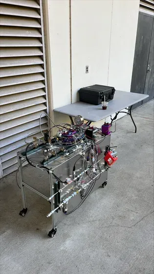
Duke AERO's liquid propulsion feed system: solenoid valves, a pressure gauge, and braided propellant lines on the test cart.

EST. 2023

REDEFINING LIMITS,
LIQUID PROPULSION

The Liquid Propulsion Division is Duke AERO's experimental research arm, where students get hands-on building advanced propulsion systems.

ABOUT US

SRAD liquid propulsion, built by students.

Duke AERO's Liquid Propulsion Division is developing fully in-house liquid propulsion technology — from combustion hardware and propellant feed systems to the control electronics that fire it. Every subsystem is designed, built, and tested by students, giving them hands-on experience in a rapidly evolving field.

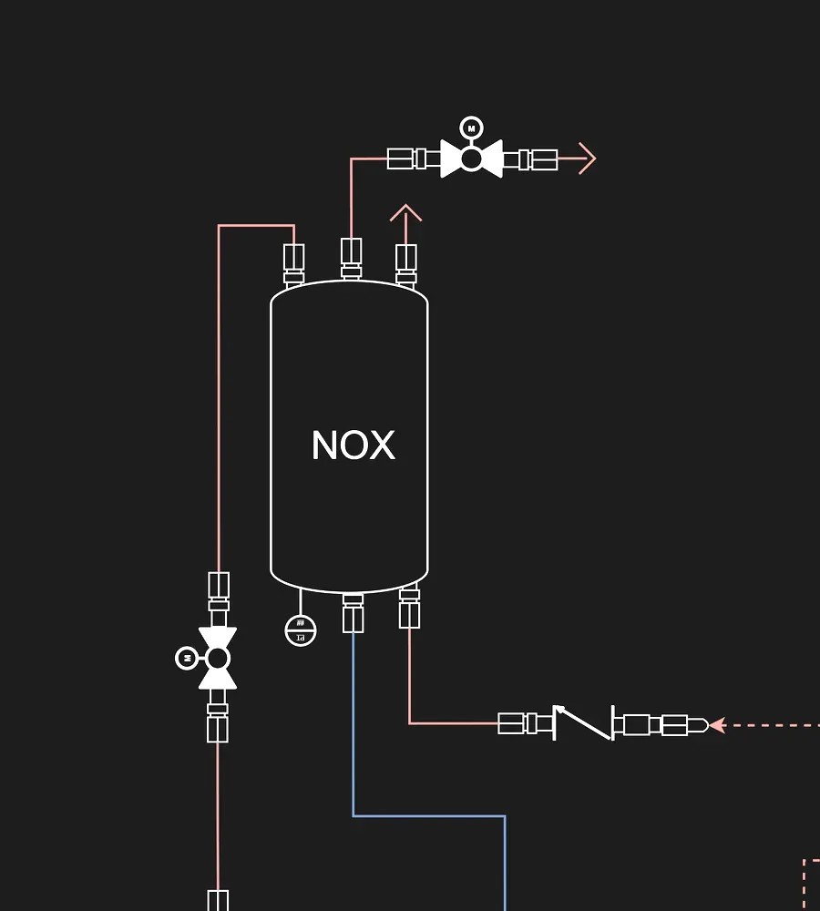
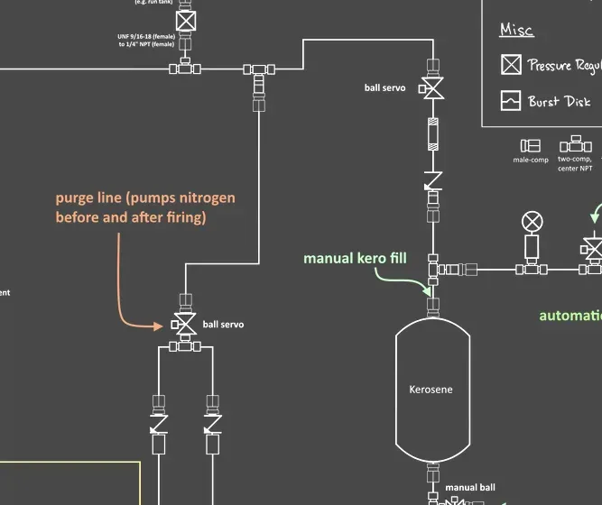
Piping and instrumentation diagram showing propellant tanks, servo ball valves, and check valves.

02

Fluid Systems

Propellant feed, pressurization, and plumbing that gets the propellant and oxidiser to the chamber safely.

ExploreFluid Systems
The division at work

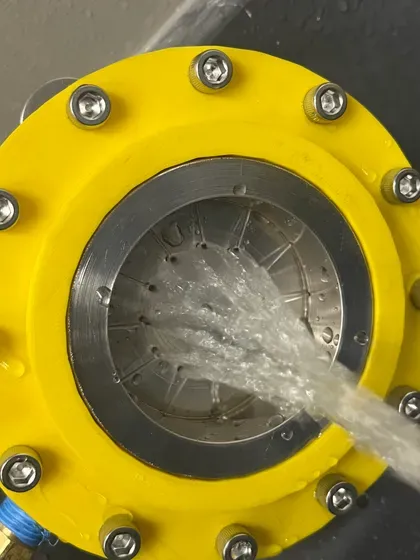
Cold flow injector spray
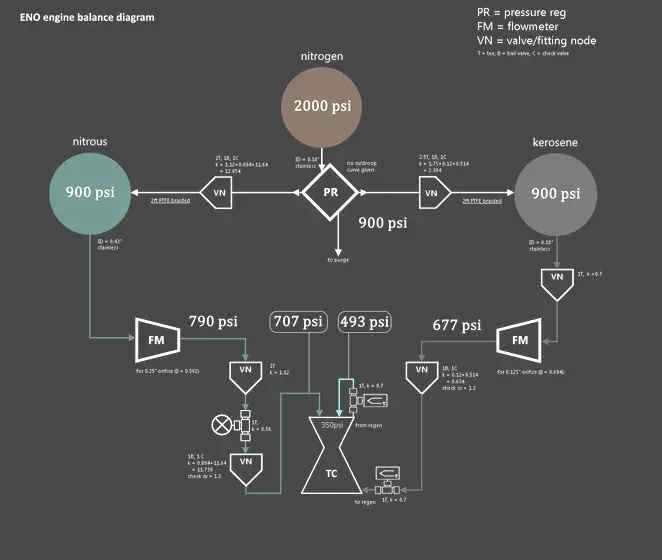
Engine balance diagram
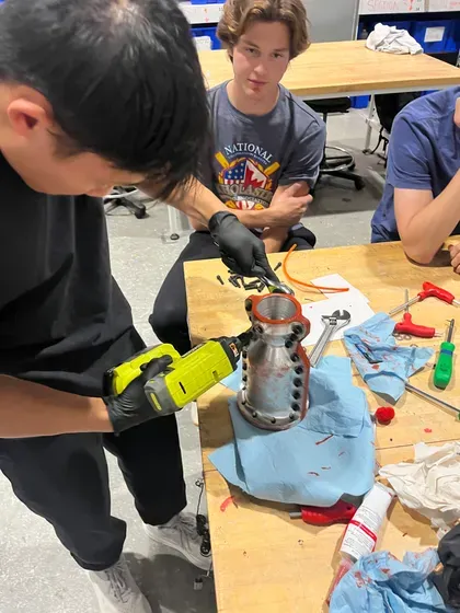
Fitting the engine halves
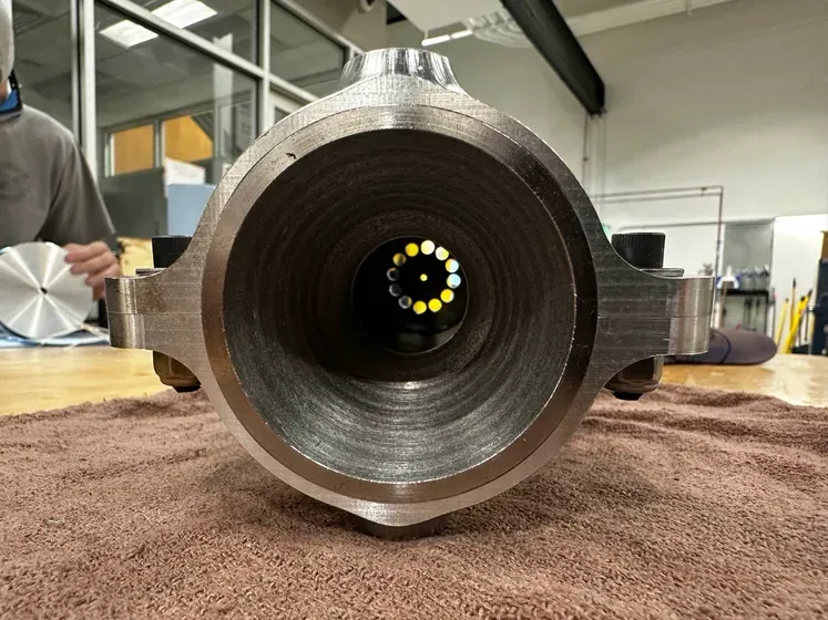
Chamber bore and injector orifices
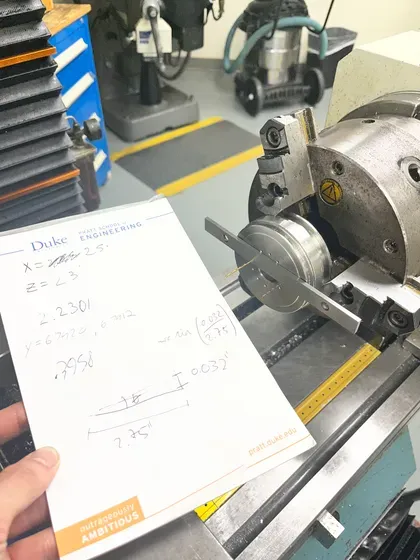
Lathe setup with handwritten calculations
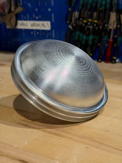
Machined tank closure
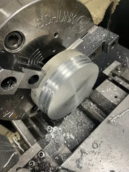
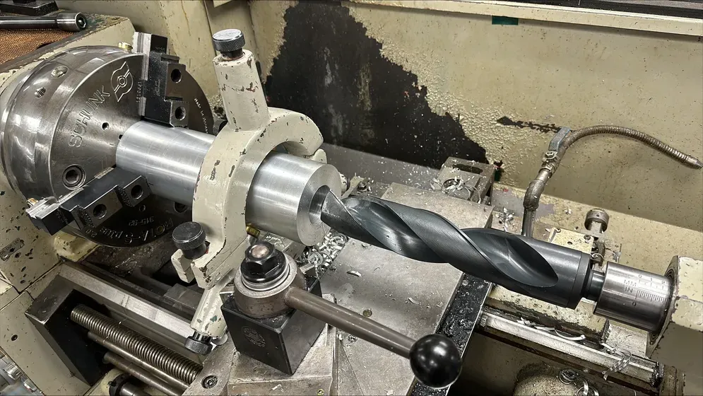
Facing a billet in the chuck
Propellant feed cart
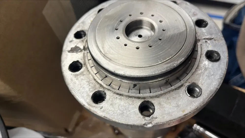
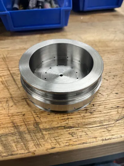
Injector face
Propellant feed schematic
Seating an o ring by hand
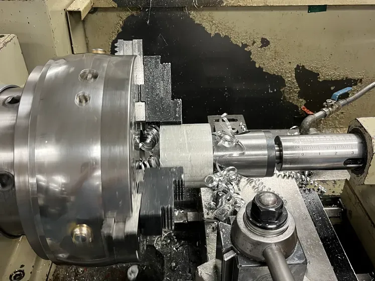
Boring bar on the lathe
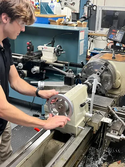
At the lathe tailstock
Cutting a bore on the lathe
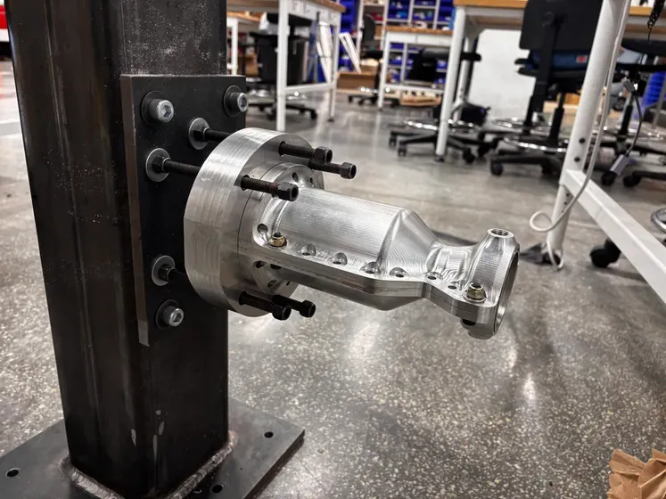
Engine mounted on the test stand
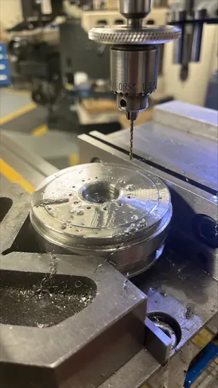
Milling an injector plate
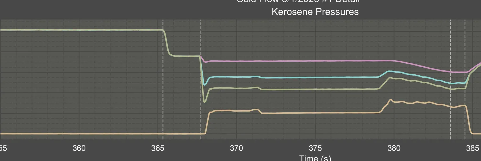
Cold flow pressure trace
Machined spool section
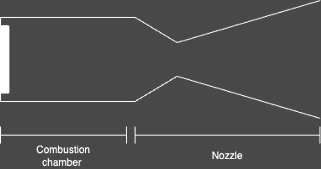
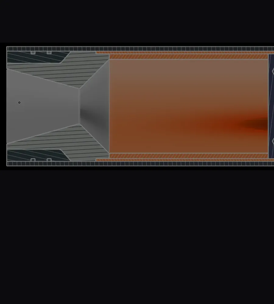
Chamber and nozzle profile
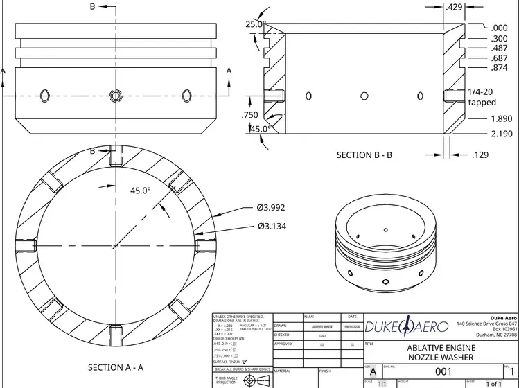
Ablative nozzle washer drawing
A supply run for parts

PROJECTS

The engines we've built so far.

Eno was supposed to reach a hot fire, but cold-flow testing turned up more problems than were worth patching, so the team started over. Prometheus is the engine that came out of that restart, built on exactly what the testing showed. Below, each workstream is real hardware someone on the team designed, machined, or wired themselves.

  1. 2023–2026

    Project Eno

    Concluded
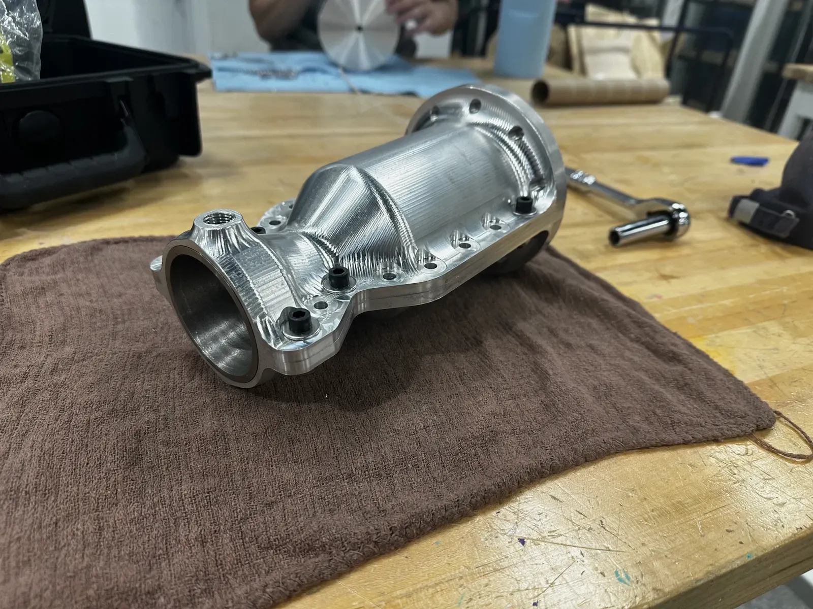
    The assembled clamshell engine resting on a workbench, bolt holes running the length of the flange where its two machined halves meet.

    Take a clamshell-architecture engine from design through to a hot fire. Cold flow testing exposed too many problems with the clamshell design — among other issues — to carry it forward. The team redrafted rather than patched it, and Eno's test data became the foundation Prometheus is designed from.

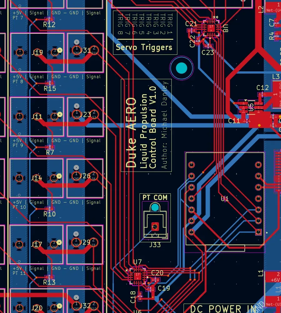
    • 01Engine Control & Measurement ElectronicsA chamber-pressure tap routed through the injector centerline, plus the sensors and wiring that read it during cold flow.
    • 02Tanks & Feed SystemNitrogen-pressurized kerosene and N2O tanks, run pressure-fed rather than pump-fed to keep the system simple.
    • 03Engine DesignThe regeneratively cooled clamshell chamber and cone injector, atomizing kerosene and N2O by collision at the injector face.
    Learn more about Project Eno
  2. 2026–present

    Project Prometheus

    Active
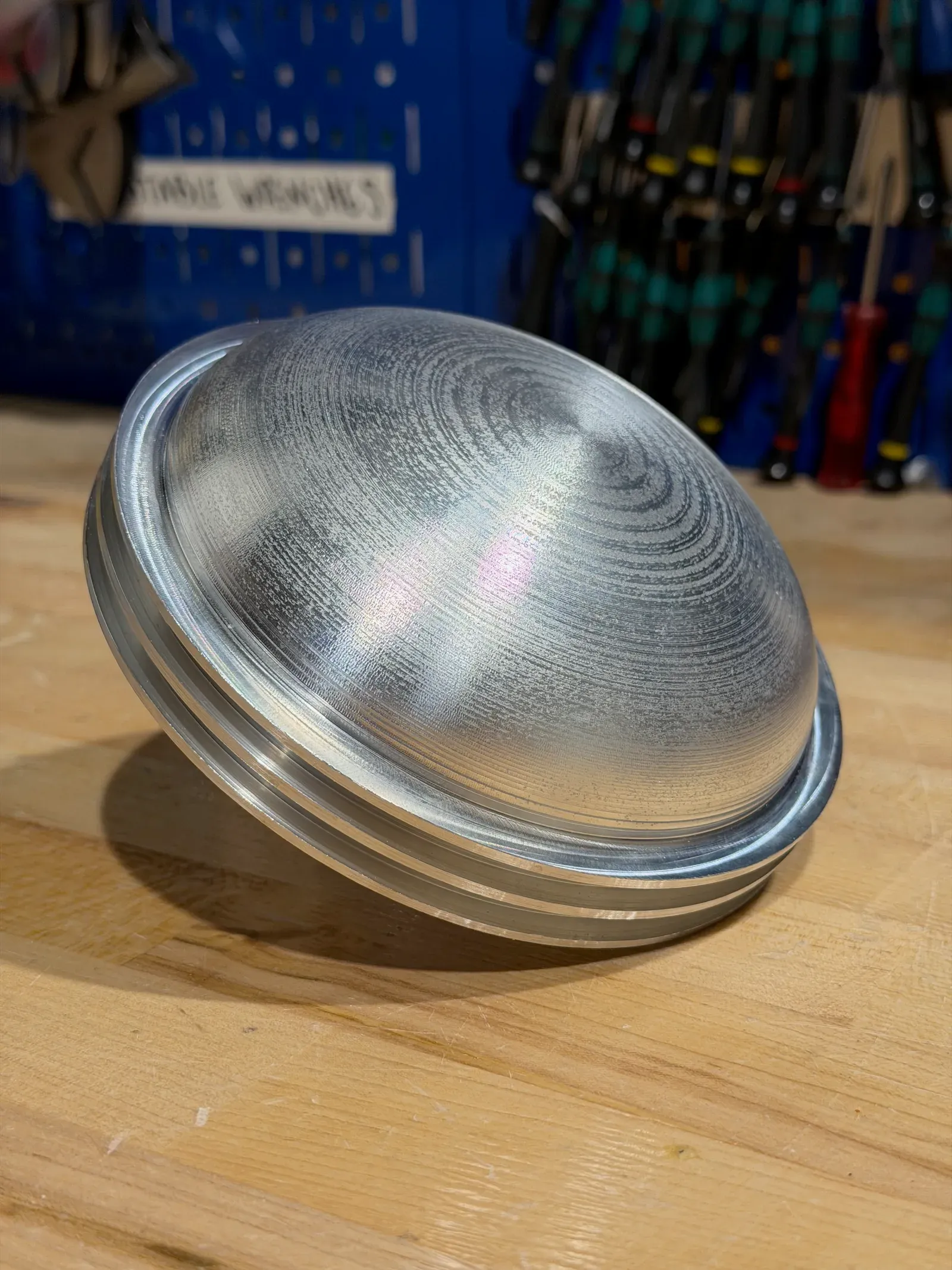
    A machined tank closure resting on a workbench, the concentric tool marks left by the lathe still visible across its domed face.

    A clean-sheet redesign built on what Eno measured, aimed at getting from drawing to hot-fire test vehicle in as little time as possible.

    • 01Engine CoreThe regeneratively cooled chamber and injector that mix and burn propellant to produce thrust.
    • 02ElectropumpAn electrically driven pump, plus the motor and controller that run it, feeding propellant to the engine at high pressure.
    • 03Flight Tanks & Feed SystemThe tanks that carry propellant in flight and the plumbing that routes it from tank to engine.
    • 04Ground SystemThe igniter, propellant fill system, and test stand/deluge that support ground testing and launch.
    • 05Controller & Active PressurizationThe master controller that sequences a firing, and the pressurization valves and power that hold tank pressure in range.
    Learn more about Project Prometheus