
02
Fluid Systems
Fluid Systems owns the path from tank to injector: pressurization, propellant routing, and the valves and interlocks that make a test sequence safe to run and, more importantly, safe to abort.
From tank to injector
We bring fuel, oxidiser, and pressurant to the engine through a connected system of tanks, regulators, and plumbing. The layout has to account for both the flow paths and how the hardware fits around the test stand. Our work connects the propellant supply to the conditions the engine needs.
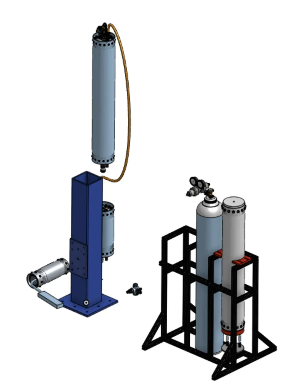
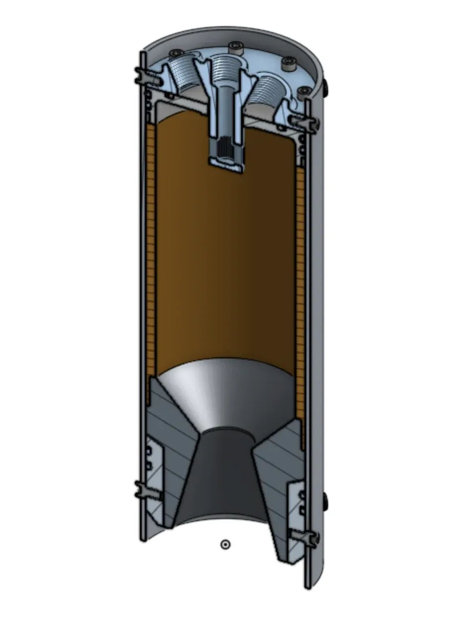
The tanks and test stand arranged in CAD, and a propellant tank in section.
Designing the tanks
The propellant tanks are our own design rather than bought hardware. Each is a cylinder closed by a machined dome that carries the ports on its face, seals against the tank wall on a pair of O-ring grooves, and takes the bolt load through a ring of lugs around its rim. The closures start in CAD and finish on the lathe, turned from solid stock in the same shop as the engine parts.
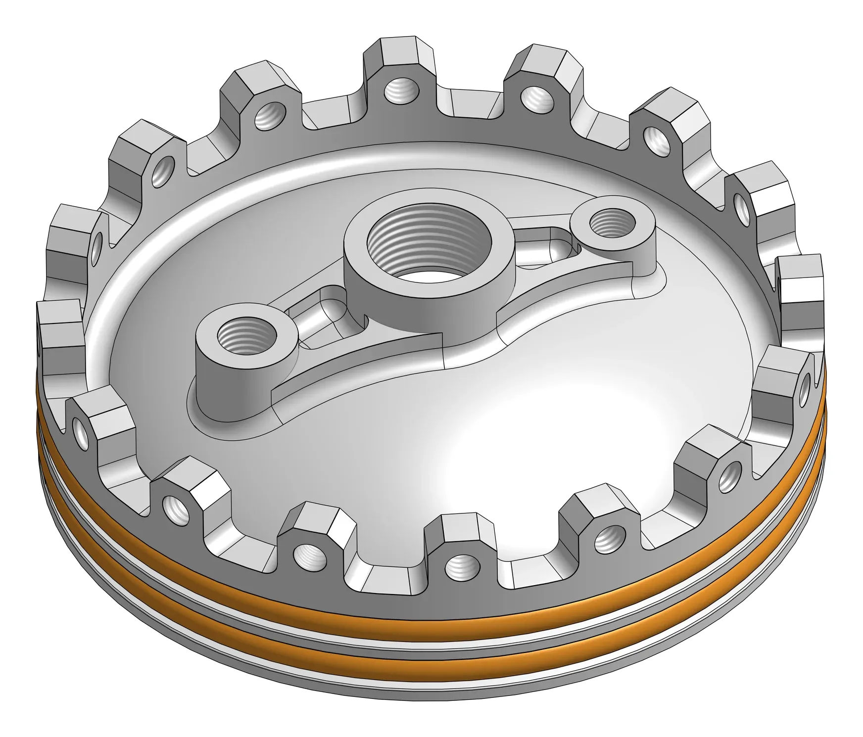
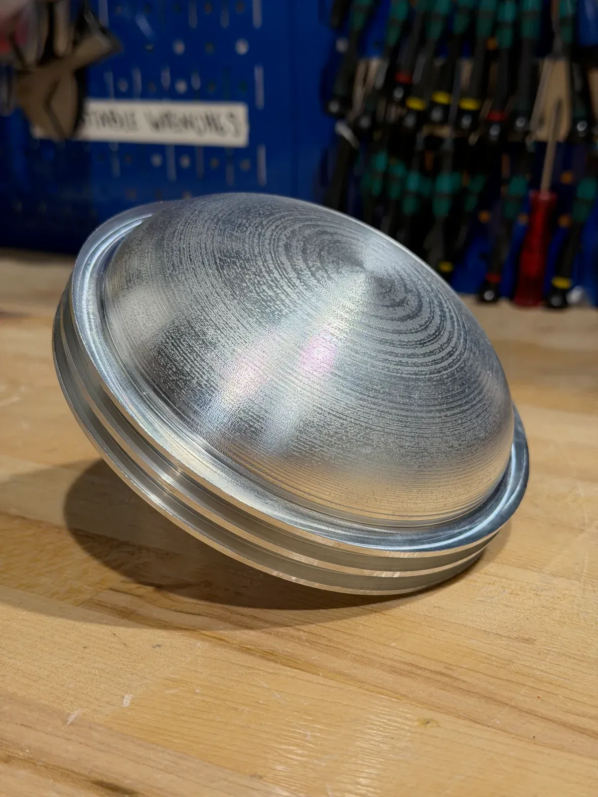
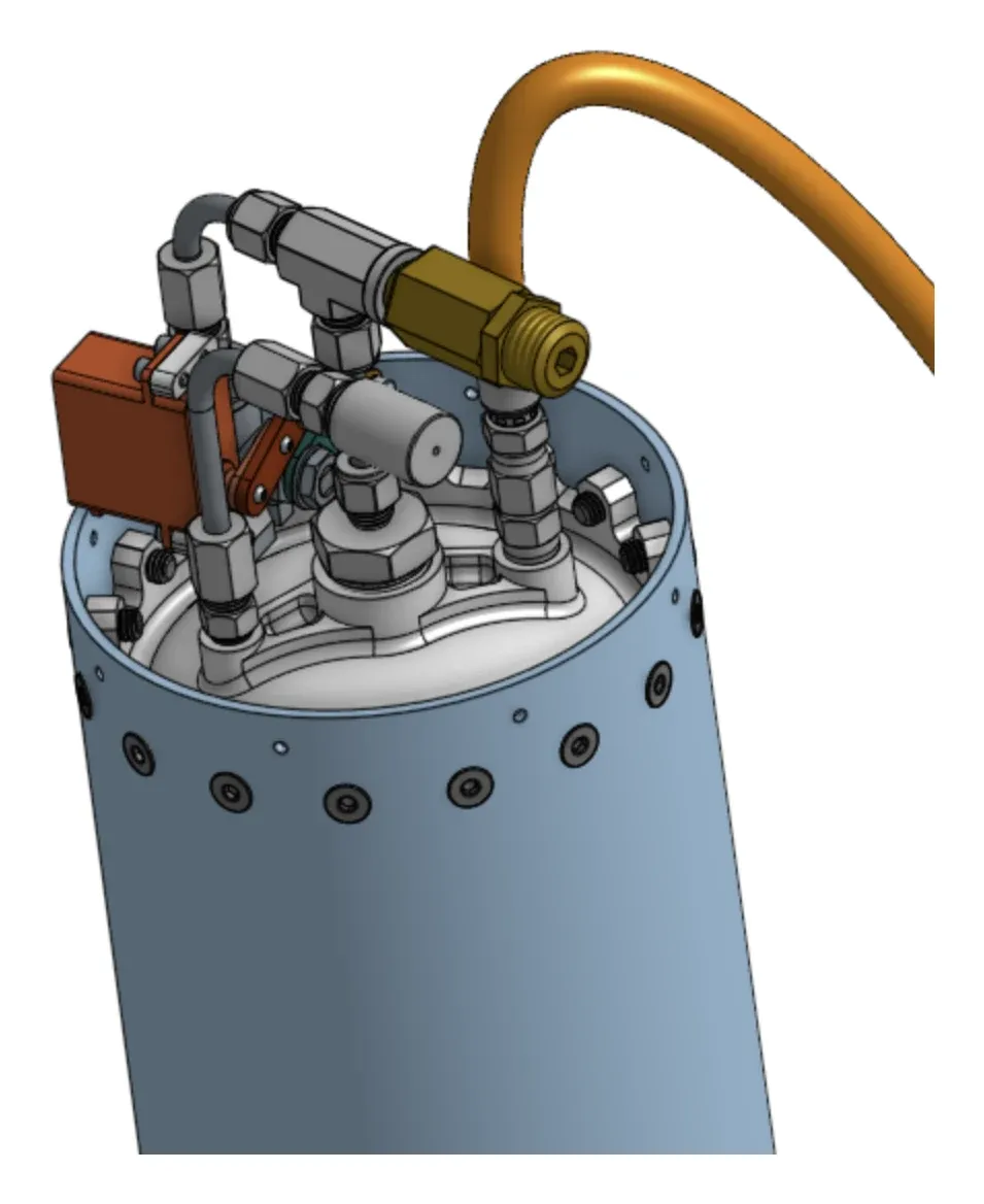
A tank closure in CAD, a closure turned on the lathe, and the fittings that land on the tank head.
Routing & control
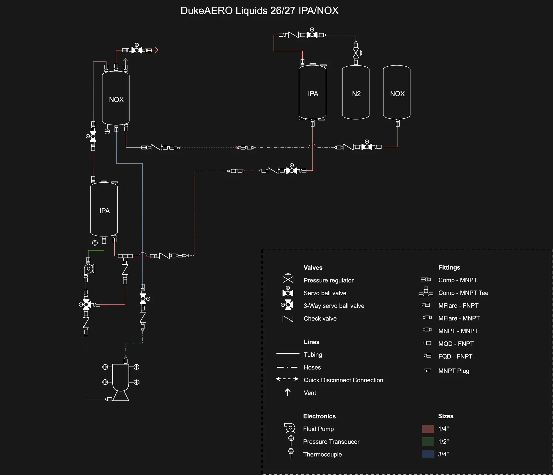
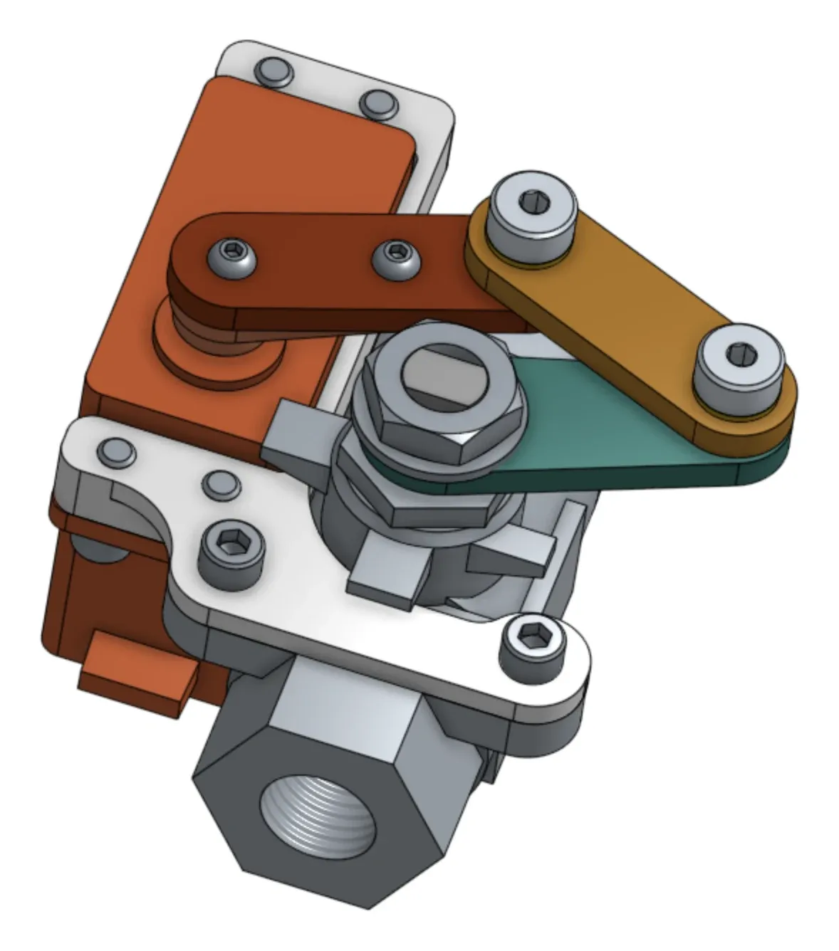
The piping and instrumentation diagram maps how the system connects, from pressurisation to the engine inlet. Servo ball valves, three-way valves, and check valves manage the flow paths, while pressure transducers and thermocouples provide measurements. We work with Electrical & Controls to connect that hardware to the test sequence and shutdown controls.
Building the connections
The work comes together on the stand, where tanks, lines, valves, and sensors become one system. Fluid Systems works alongside Combustion Devices to connect the feed system to the engine, and alongside Electrical & Controls to make it operable. Shared shop work and integration bring the plumbing, engine, and electronics together for testing.
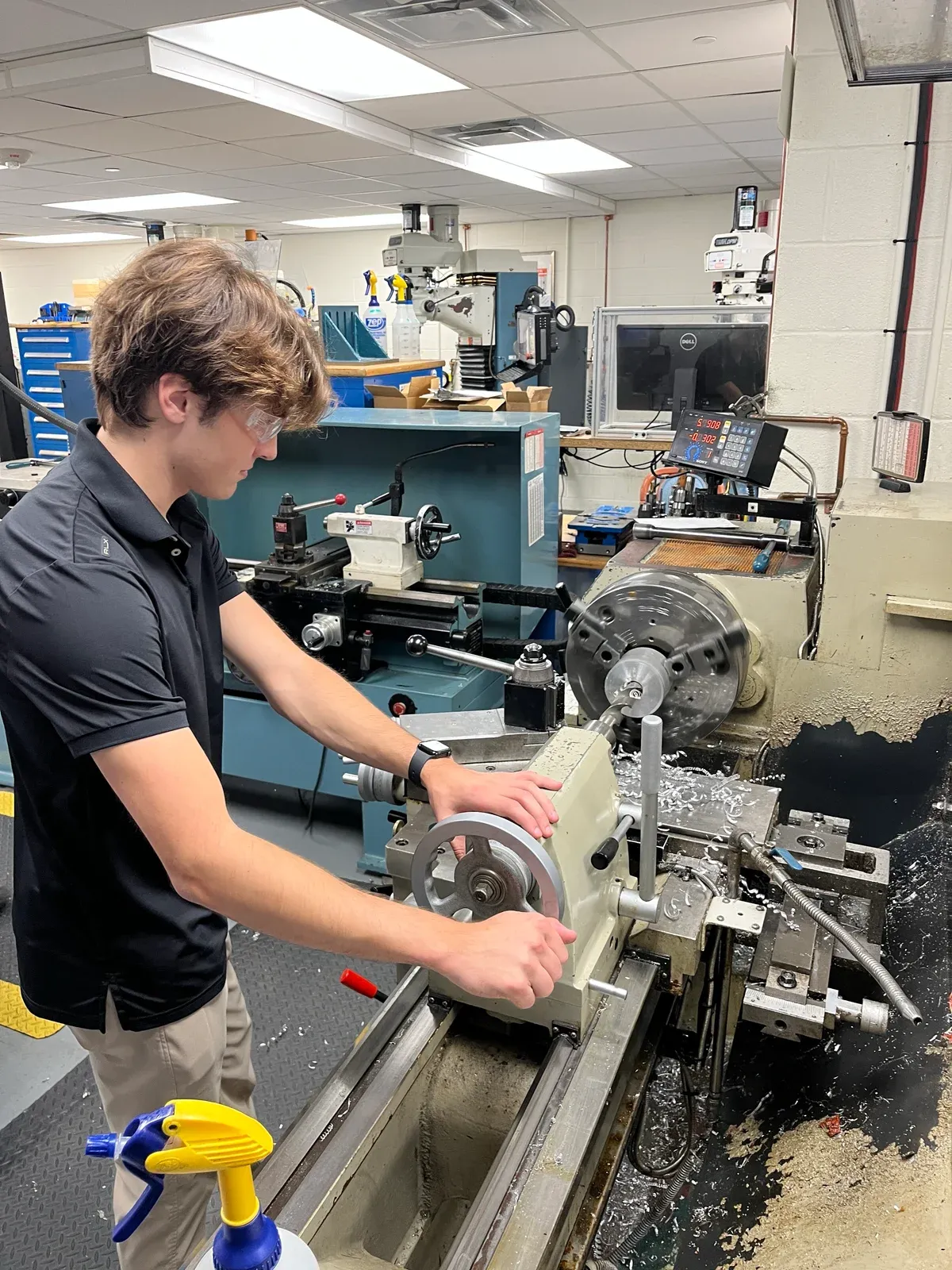
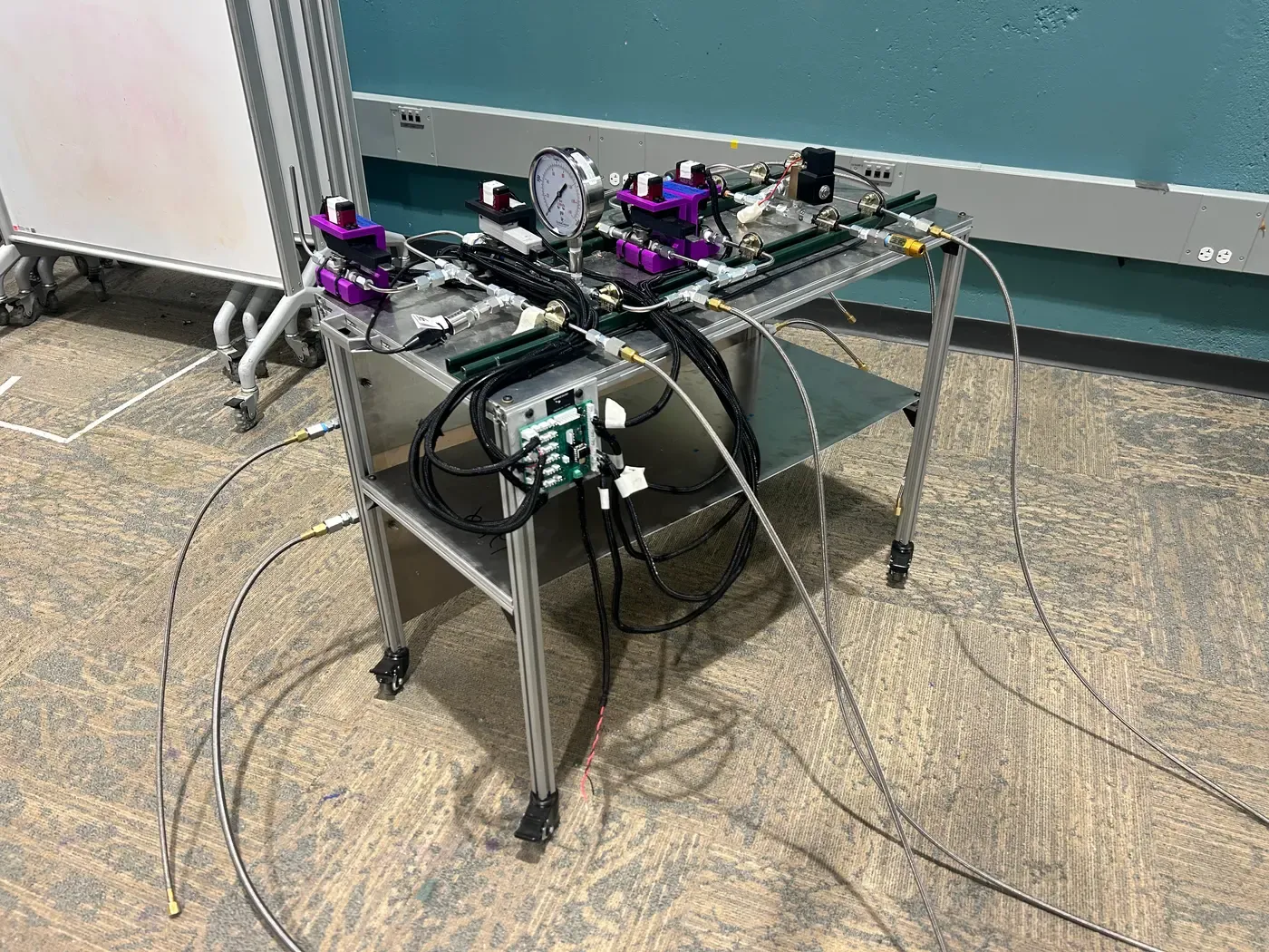
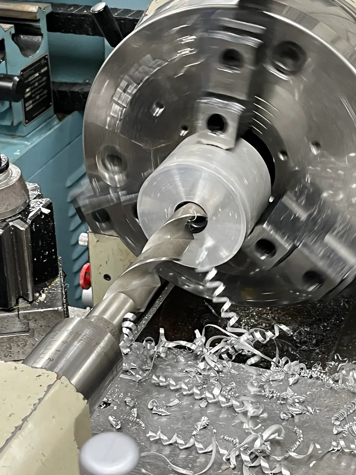
Shared shop work alongside the assembled test plumbing.