2026–present
Project Prometheus
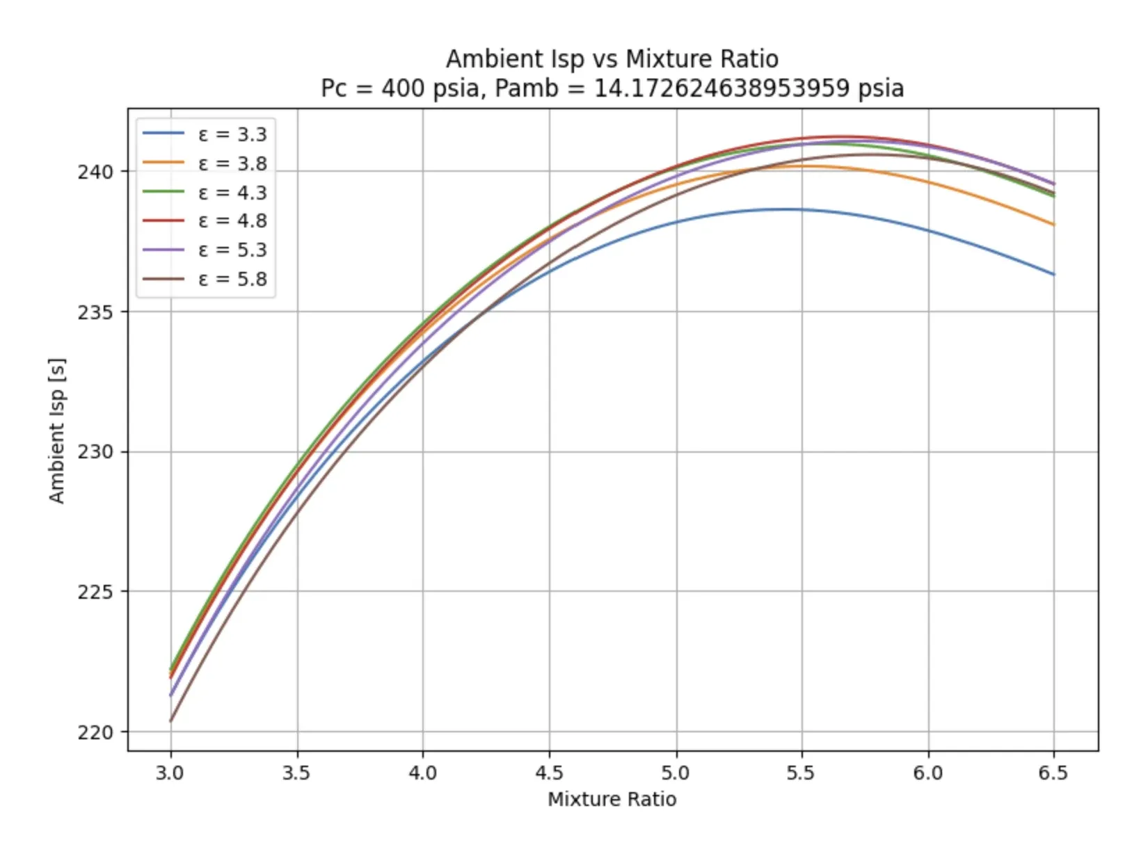
A regeneratively cooled clean-sheet redesign, aimed at hot fire.
A clean-sheet redesign built on what Eno measured, aimed at getting from drawing to hot-fire test vehicle in as little time as possible.
Workstreams
- 01Engine CoreThe regeneratively cooled chamber and injector that mix and burn propellant to produce thrust.
- 02ElectropumpAn electrically driven pump, plus the motor and controller that run it, feeding propellant to the engine at high pressure.
- 03Flight Tanks & Feed SystemThe tanks that carry propellant in flight and the plumbing that routes it from tank to engine.
- 04Ground SystemThe igniter, propellant fill system, and test stand/deluge that support ground testing and launch.
- 05Controller & Active PressurizationThe master controller that sequences a firing, and the pressurization valves and power that hold tank pressure in range.
The redesign
Prometheus is Duke AERO Liquid Propulsion’s clean-sheet successor to Eno: a regeneratively cooled engine, designed from the ground up rather than patched forward from the clamshell architecture. Regenerative cooling routes propellant through channels machined into the chamber wall before it reaches the injector — the chamber cools itself with propellant that was headed into combustion anyway, rather than relying on a single-use ablative liner.
TODO(content): confirm program start date, target propellants, and thrust/chamber pressure once finalized — nothing here should guess a number.
What changed from Eno
Eno’s cold flow campaign is the direct reason Prometheus looks the way it does. Regenerative cooling and a clean-sheet chamber replace the clamshell’s bolted-halves structure, and the feed-system behavior Eno’s campaign measured carries forward into how Prometheus’s fluid systems are sized.
TODO(content): spell out the specific design decisions Eno’s data drove — which parameters changed, and by how much — once the design record is ready to publish.
Flight tanks and feed system
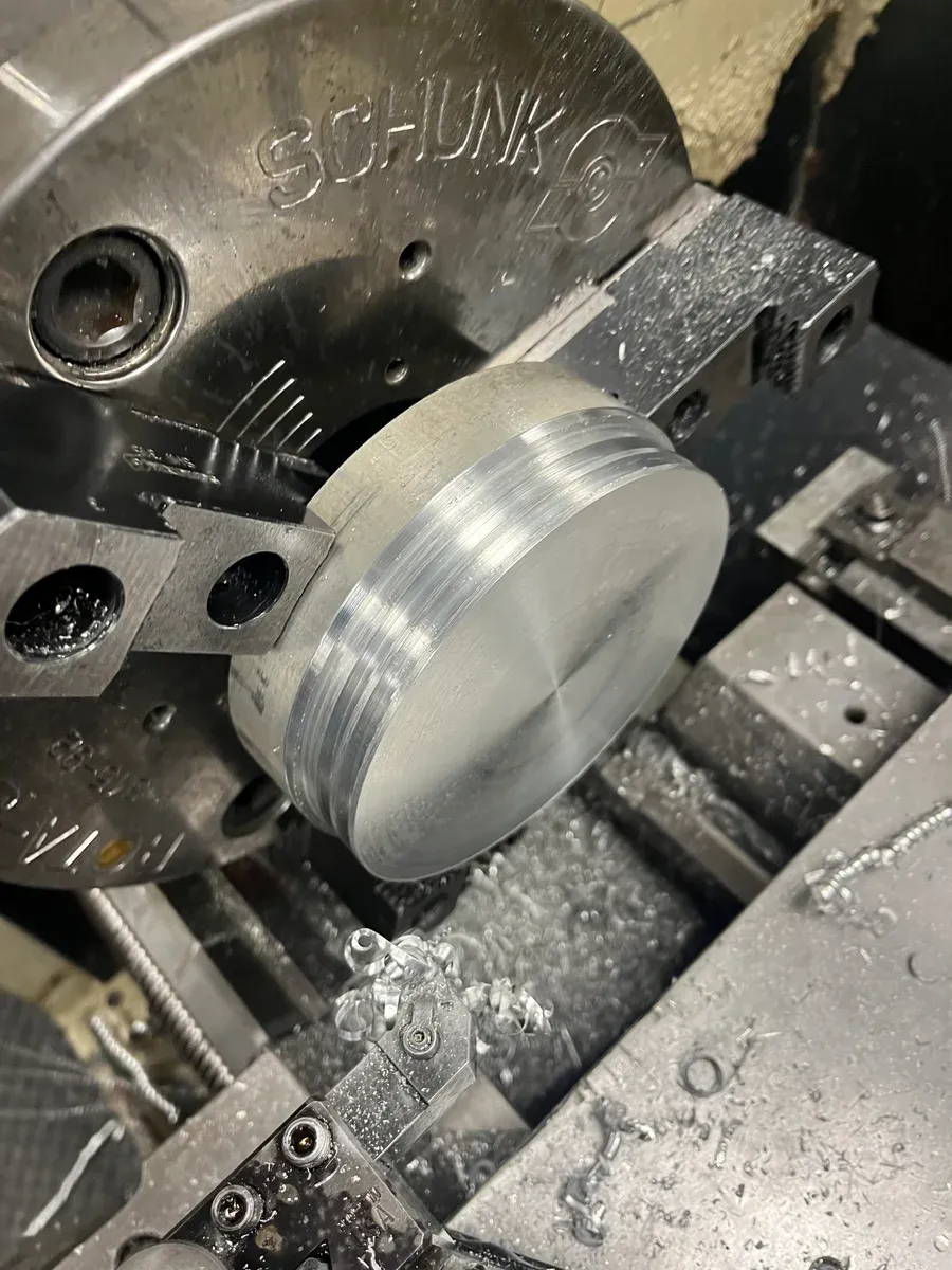
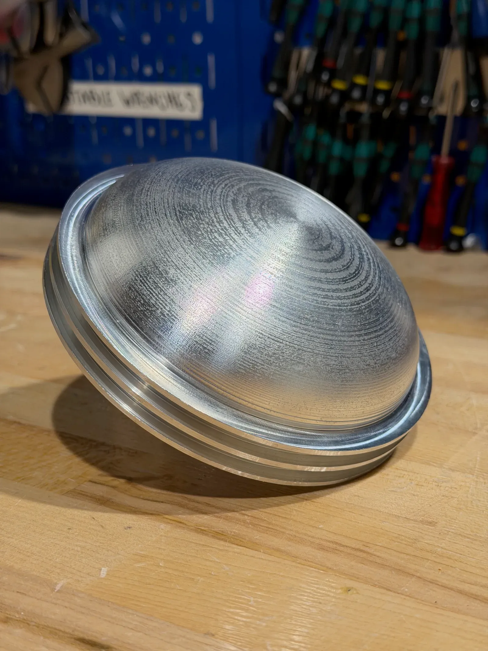
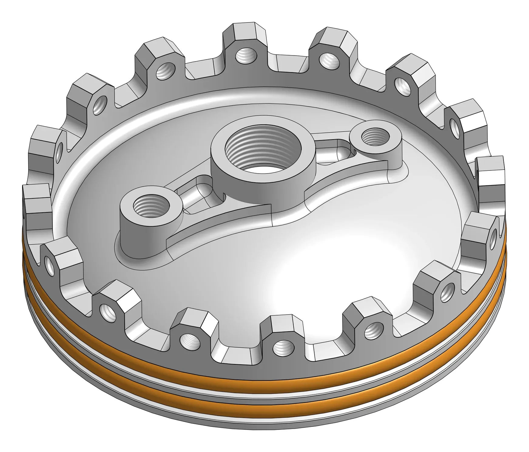
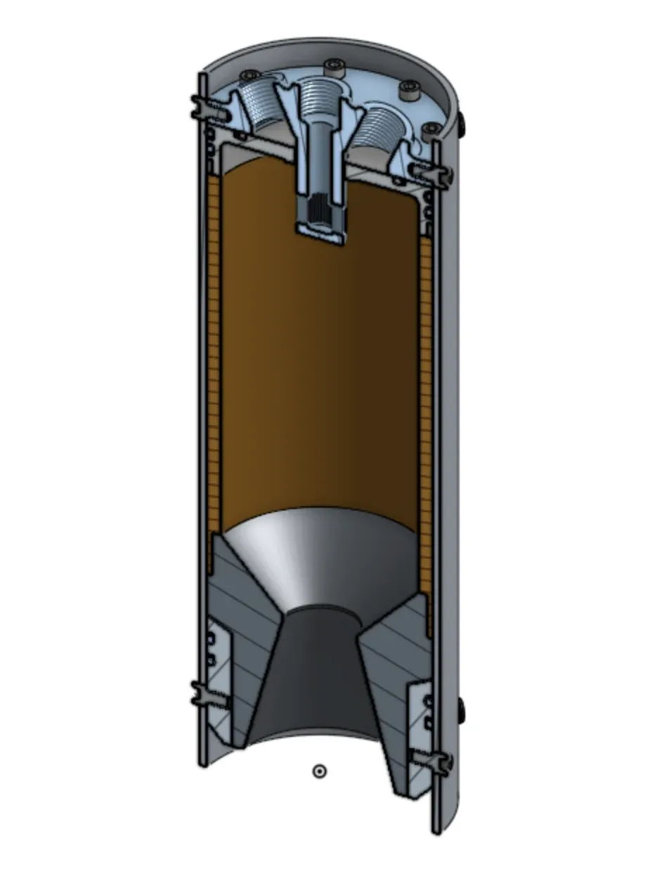
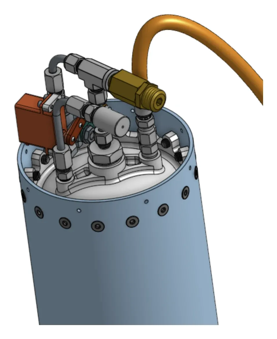
The tanks are the part of Prometheus furthest along into hardware. Each is a cylinder closed by a machined dome: the ports land on its face, a pair of O-ring grooves seals it against the tank wall, and a ring of lugs around the rim carries the bolt load. The first closures are already turned — the one in this page’s banner came off the lathe in the shop — with the feed side around them drawn but not yet built: the fittings that land on the tank head, and the linkage that lets an actuator drive a valve from beside the line rather than sitting on top of it.
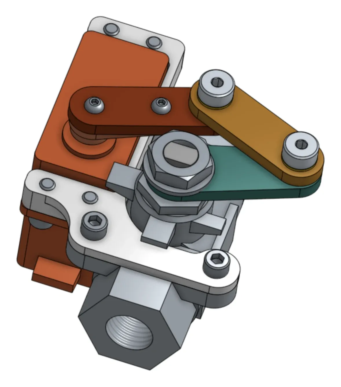
TODO(content): tank volumes, operating and proof pressures, and material once the design is frozen — and whether the electropump or a pressure-fed system drives the flight configuration.
Avionics and ground control
Every earlier cold flow ran through a wired setup: a mess of cables, a handful of protoboards, an Arduino UNO, and an external DAQ, all driven from a laptop running LabVIEW over a long USB run. It worked, but it cost hours of wiring and troubleshooting before each test, and a liquid engine doesn’t forgive a flaky connection the way a bench experiment does. The boards that sequence Prometheus are the division’s answer to that pile of wires.
Control board V1.0
V1.0 folds sensing, actuation, and power into a single board built around an ESP32-C3, talking to a laptop over WiFi instead of a USB tether — the same link carries telemetry out and servo commands in, so the DAQ and its cabling come out of the test setup entirely.
Sensing runs through three 8-channel TLA2518 ADCs sampled over SPI, with enough of their combined 24 channels broken out to give the board its twelve-channel pressure-transducer interface, each channel hardware-averaged to cut noise before it ever reaches software. Actuation runs through a PCA9685 PWM driver, offloading servo timing from the MCU entirely and giving the board’s eight-channel servo bus 12-bit resolution on every valve. Separate buck converters keep servo power and logic power on their own rails off the same 12 V input, and every field connection — PTs, servos, power — lands on a keyed JST connector, so a cable can’t go in backwards during a rushed pre-test hookup.
Ground control
The board pairs with a Python ground-station application that gives the operator a command console, live per-channel servo state, and a real-time plot of all twelve pressure channels running through a configurable moving average. Valve actuation can be driven live from the console or from a timed sequence script, so an abort or a firing sequence runs the same way every time instead of depending on an operator’s timing. Every run — telemetry and actuator state alike — logs to CSV for teardown after the test.
What cold flow found
Running V1.0 through cold flow cut electrical setup from hours to minutes and more than doubled pressure-transducer polling, from 40 Hz to 100 Hz, once sampling moved onto dedicated hardware instead of a DAQ. Testing also found the board’s limits: servo current capacity was undersized for sustained actuation, and analog routing on a single board left the pressure readings more susceptible to noise than the team wanted. Both are the reason there’s a V2.0.
Board V2.0
V2.0 splits the single board in two — a control board carrying the MCU and servo bus, and a separate sampling board carrying pressure, thermocouple, and load-cell inputs — so switching noise from servo drive never shares a board with the analog signals it would otherwise corrupt. The MCU moves to an ESP32-S3 with onboard LoRa and local data logging, adding a wireless fallback and an on-board record independent of the ground-station link. Sampling gains thermocouple channels through an AD8495 amplifier and load-cell channels through an HX711 ADC, and servo power moves to a higher-current buck converter sized for the draw V1.0 undersized. The two-board stack is built and is now being brought up ahead of its first cold flow.
TODO(content): confirm current V2.0 status (bring-up vs. first test) before this goes live, and update the paragraph above to match.
Where Prometheus stands today
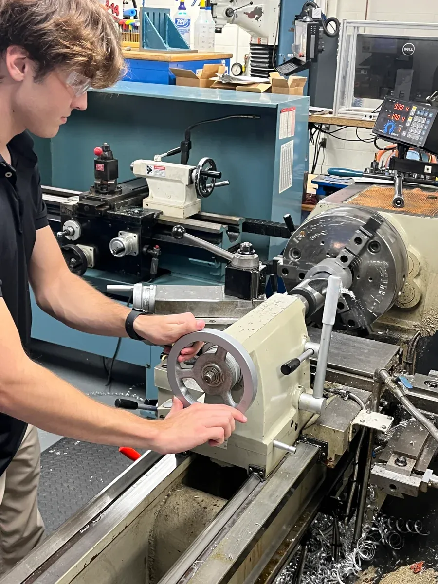
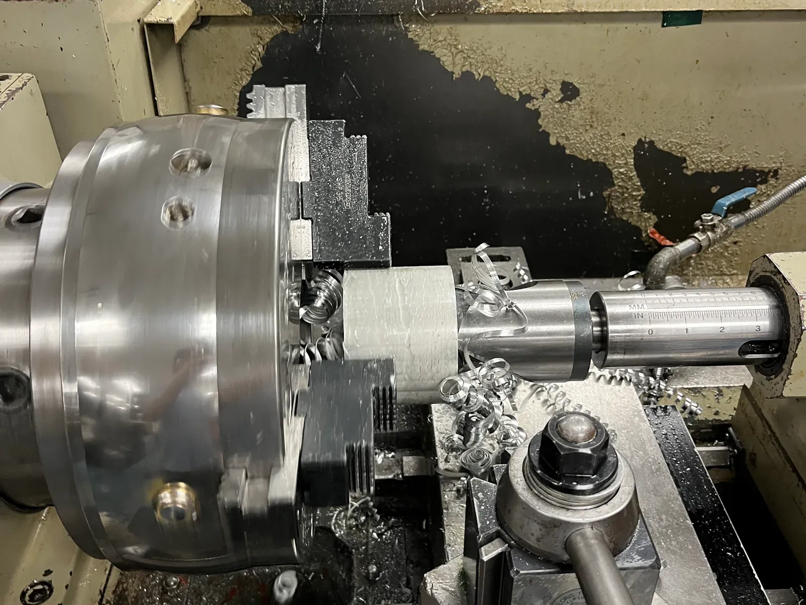
The photographs below are from the shop this term, as the first Prometheus parts come off the lathe. The project is active, aimed at getting from drawing to a hot-fire test vehicle in as little time as possible.
TODO(content): current build/test status and the next milestone on the path to hot fire — keep this section current as the campaign progresses rather than letting it go stale after publishing. Name the parts in the build photographs below, too; their captions describe the cut, not the component.
From the build